 EN
EN BG
BG
TFT LCD display with 320x240 resolution for
RASPBERRY PI
The project is based on following publication: SpritesMods.com
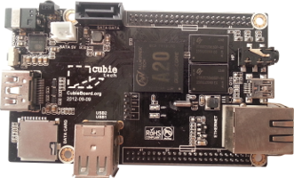
RASPBERRY PI is credit card size computer, which price is only about 35Euro. This makes it accessible to a wide range of people.
Despite its low price it is equipped with Broadcom's SoC BCM2835, it contains very powerful ARM1176JZFS CPU running at 700MHz, with floating point, Videocore 4 GPU capable of BluRay quality playback, using H.264 at 40MBits/s. Unfortunately it needs a TV or monitor to display information.
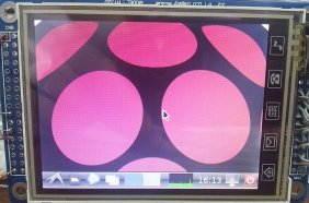
The goal of this project is to show how to change this TV with TFT LCD display 320x240 resolution, which is enough for presenting of simple text and even video information.
Such displays are fairly common and cheap. Can be found at Ebay for about $20. Their only disadvantage is that it needs at least 21 I/O lines to be handled. 16 data bits, SC, RS, RD, WR, RESET
The project avoids this disadvantage, with using SPI bus instead paralel. This way you need only 3 I/O lines to communicate with the LCD.
There is a disadvantage when using serial communication - low frame rate. But this low frame rate is enough for displaying static or slow changing information.
In addition there is touch panel which can replace keyboard and mouse. We need 3 more I/O lines to drive it.
The first step is building SPI to parallel data converter. Its electrical circuit is:
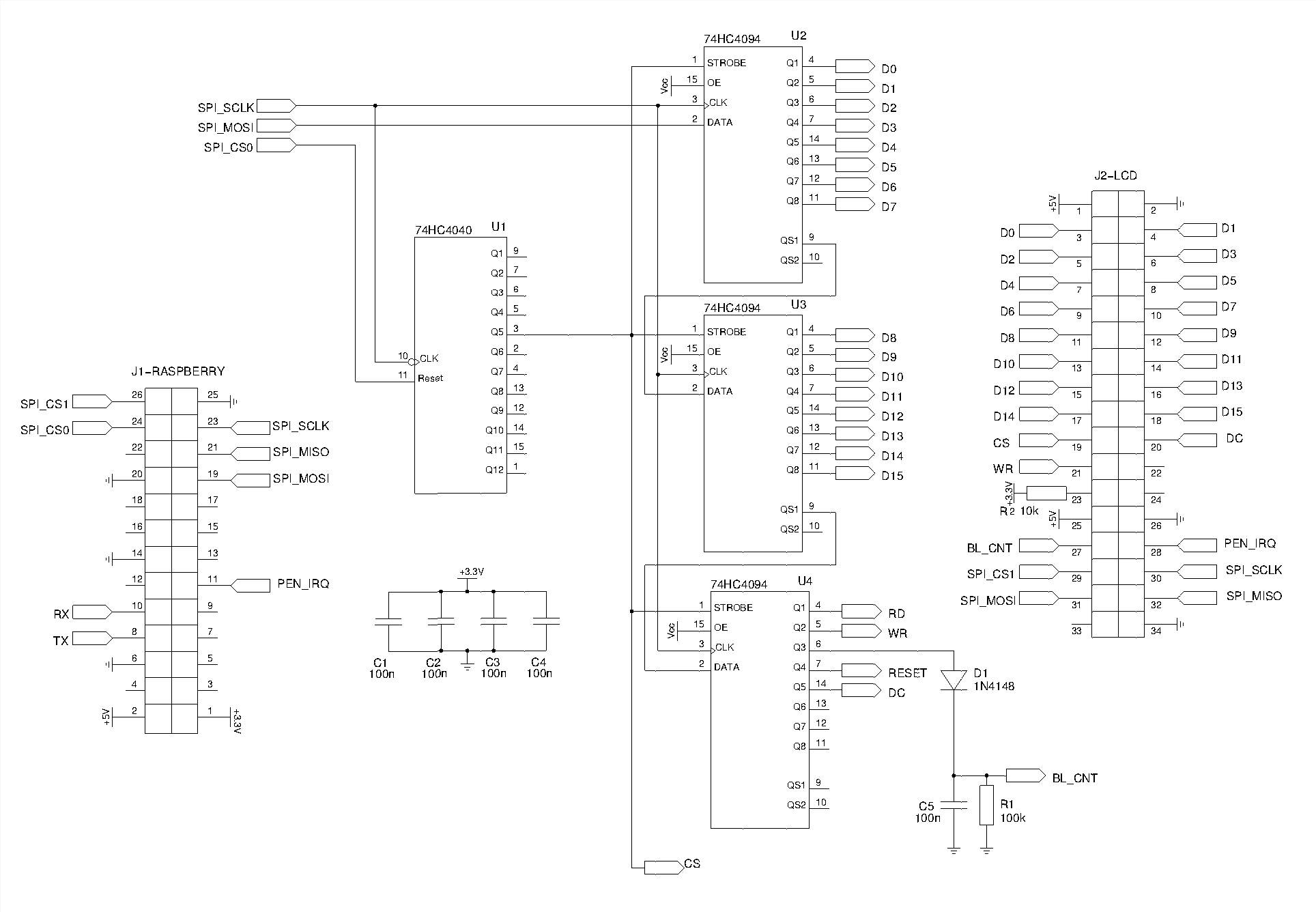
A little explanation of how the circuit works:
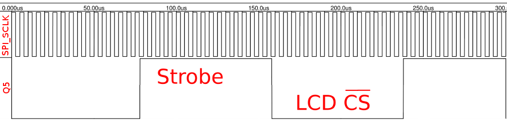
The serial data are latched in the cascade connected shift registers CD4094 through SPI_MOSI on rising front of SPI_SCLK. The CD4040 counts to 32 when it is enabled by SPI_CS0. After 16th clock pulse its Q5 output goes high. It causes every changing of internal state of shift registers to affect its parallel outputs. After 32th clock pulse Q5 goes low. It "latches" the state of shift registers. In the same time entering the data to LCD is enabled by its CS input.
This way by sending 4 bytes to SPI bus you can transfer 16 data bits and other driving signals (CS, DC, RD, WR, BL_CNT) to LCD display. Using this circuit you can increase the speed of data transfer to the LCD because it isn't necessary to select SPI bus for every byte sent which is very slow proces.
The next step is to write a driver for so described converter. Or download already compiled from here and just copy it to Raspberry's SD card
If you choose the long way you can follow next instrictions:
1. Follow the instructions from here, but before compile the kernel you should apply this patch ssd1289-linux.3.6.11.diff to the sources by using "patch -p1 -i ssd1289-linux.3.6.11.diff" from directory ~/linux
2. Comment blacklist spi-bcm2708 in the file /etc/modprobe.d/raspi-blacklist.conf
3. Add into the file /etc/modules a line with content ssd1289
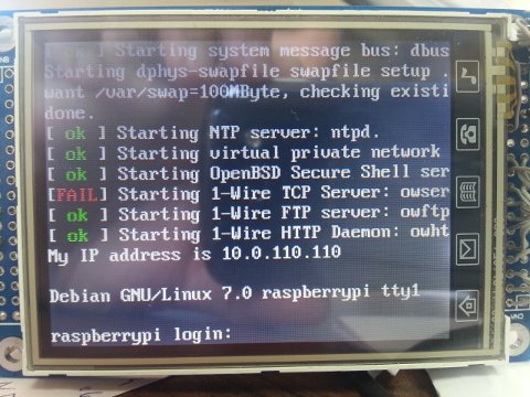
4. After reboot the module ssd1289 should be loaded. You can check this by "lsmod | grep ssd1289"
5. The easiest way to check if LCD is working is by redirecting console to new frame buffer "con2fbmap 1 1" or by staring X with "FRAMEBUFFER=/dev/fb1 startx"
6. If you want this redirecting to be permanent you can change content of the file /boot/cmdline.txt to: "dwc_otg.lpm_enable=0 console=ttyAMA0,115200 kgdboc=ttyAMA0,115200 console=tty1 root=/dev/mmcblk0p2 rootfstype=ext4 elevator=deadline rootwait fbcon=map:1 fbcon=font:ProFont6x11"
Comments:
hi, ebay sale this Touch TFT LCD Display Module with SPI Interface. I think this is really nice, but I want to know, can I use the driver with this LCD??
thanks
Hi Valdodov,
I have followed the schematic and every thing seems to be in order. However, CE0 is always high, which resets the Binary counter. Is that supposed to be the case ?
Hi joe and Alan,
Q5 goes LOW (this activates LCD's CS) after 16 clocks and stays in this state for next 16 clocks. After 32th clock everything latches to the LCD.
if like Joe mentioned here. You said 16 clock cycles of the SPI. How can it be possible for the 3rd shift register have anything in it ?
I am just curious . Thank you
I congratulate you on the project. However, i want to clarify. isnt Q5 in the ripple counter every 32 not 16?
Hi Valdodov,
I am trying to get this LCD to setup with my raspberry pi, but I don't have any experience in either how the Pi environment works or where I need to go to change those files.
Is it possible to do if I have raspbian installed on my Pi? If so, is it possible for you to walk me through at least maybe through the beginning process of setting up the config and kernel files?
I would really appreciate it if you could help me out.
Thanks,
Kush
Hi , I have ITDB02-3.2S LCD with SSD1289 Controller , can I used your driver? thanx
hey ,first of all thank you for the tutorial ,most informative.

i have a problem though ,i have a 2.8" 18-bit color TFT LCD with touchscreen breakout board with a ILI9325 controller from adafruit ,here is the link for it :http://www.adafruit.com/products/335
here is two photo of the display's pins :
dfrom what i've come to understand is that this display needs 8 pins wired for the data input output,4 for the touch screen,4 for the control inputs,backlight and power ofcourse
but i still can't get it to work ,how to wire the data and control pins to a raspberry pi model B ,do i have to wire them to gpios of my choice,and when loading the fbtft module assign them one by one ? and if so what module should i use.
ps:i've tried this and didn't work
can any one please help with this ,its really important
thanks in advance
Hi hikmet,
The answer is - nowhere.
You can't read from the LCD. You can only write to it.
Hi Valdodov,
Where do we connect the RD pin from 74HC4094
Hi Ramses Leon,
the easiest way is first to apply the patch and then modify drivers/video/ssd1289.c file. After that you can compile the kernel.
The PEN_DOWN_STATE_PIN is defined in arch/arm/mach-bcm2708/bcm2708.c file you could change it to:
#define PEN_DOWN_STATE_PIN 11
Hi Efel Nava,
the linux touch screen driver ads7846 supports both ads7846 and ads7843 chips.
The only thing you have to do is to specify correct chip in struct ads7846_platform_data
static struct ads7846_platform_data ads_info = {
.model = 7843,
..........
}
This structure is placed in arch/arm/mach-bcm2708/bcm2708.c file. If you appply my patch you will find it.
Hi,
I want to try the same with a 16-bit ILI9320 controller and a TSC2046 TP controller (it suppose to be the upgrade version of the ADS7846).
I have some questions,and I hope you could answer.
I'm new in the driver development so I do not know if I can just modify the .diff you provide with the registers and init sequence of the ILI9320 and later compile using your instructions.
Also how do you define that the PEN_DOWN_STATE_PIN is in the GPIO #11 (like in your diagram) instead of the #17 in the .diff
Thanks in advance
Greetings,
First of all I want to congratulate your great job and thank you for sharing your knowledge. I'm currently trying to do the same. I was able to connect a ILI9325 2.4" but I has no idea of how to apply the touch panel driver. As I can see, you have touch screen support, but I have two questions, the driver is for the ADS7846, does your TFT board is built-in that driver? I have a ADS7843 and according to the datasheet is compatible with ADS7846 only if the VREF is modified. Can you give me any suggestion or advise to enable the touch panel?
Thanks in advance
Hi Adam,
I have used +3.3V directly from Raspi.
The reason you have use 3.3V with 74hc4094 is because Raspi's and LCD inputs are not 5V tolerant.
Hi Valdodov,
did you get all 3,3V from the raspberry? I have a Display with just 3,3V Input and I read that raspis 3,3V can only give 50mA so I better create the 3,3V from the 5V, or? Is there a special reason why to use the Shift things with 3,3V? All 74HC4094 I find can be driven from 2 to 6V.
Great work!
Adam
Hi I have a 5.0 " TFT LCD touch panel ssd1963 rev 4.3, can I use your board to connect the LCD to my raspberry?
How much does it cost?
Hi lerppu,
if you want to build the PCB by your self, then do it.
First learn to use Schematic editor then PCB editor.
I can recommend you KiCad. It is free.
Good luck
Hi Carlos,
it is possibe.
You should edit arch/arm/mach-bcm2708/bcm2708.c file the part is:
{
.modalias = "spi-ssd1289",
.max_speed_hz = 32000000, // it can be .max_speed_hz = 4000000, which is 4MHz
.bus_num = 0,
.chip_select = 0,
.mode = SPI_MODE_2,
}
It is possible to decrease the spi bus speed for test circuit with HCF4094 ?
if it is possible, can you tell me how to do?
Thanks!
Hi,
Is there any chance you could share the pcb design, i have hard time routing the design i made of your schematic (i'm complete beginner) but would want to build it myself.
Hi Stefan Stoichev,
If you want I can sell you ready for use PCB. If you want LCD too you have to wait about a month for delivery.
Hi Vlado,
do you have plans to sell pre-made, ready to connect modules?
Thanks!
Stefan
Hi Theodore Flokos,
please write me to the e-mail: valdodov@gmail.com
Hello I wanted to ask you how much this board costs ready to use ? and if not ready to use at least with surface mount components soldered
and provided the other compoenents too ?
Hi Patrick,
they should work perfetly.
Hi. I've been following your work with these screens, and I'm inspired to try this project myself. I currently have six screens (linked below) laying around and I'd love to be able to connect one to a raspberry pi. They are slightly different than the screen you are using, but they have the same lcd controller. Do you think it could work?
"http://www.ebay.com/itm/261053931637?ssPageName=STRK:MEWNX:IT&_trksid=p3984.m1497.l2649"
Thanks,
Patrick
Hello Valentin,
Great work figuring this out! Would you be so kind as to contact me regarding an order? I don't see any way of contacting you.
reinierweerts (at) gmail.com
Thank you in advance,
Reinier
hello,
I am very interested in buying one of your pcb.
How do I??
Greetings.
DVDint@ymail.com
Hi Zaini Hafid,
i can't understand your question
Hi André Moreira,
it is not possible to use I2C instead SPI bus because it is very slow
is any setting again in rapsberry when I buy LCD module + SPI to parallel converter??? I really need this module
How difficult is to use i2c instead of SPI? I have some i2c port expander that supposedly can do the same thing of c4094.
Hi ,
i'm interested by making what you've done.
i have a question : is it possible to do the same adaptation with a 7" tft display touchscreen sold for arduino mega or due?
thanks
picture attached
Hi Mickey,
As I wrote before the price for PCB only is 15EURO. On this PCB you can mount SPI to paralel converter, IO expander, Real time clock and DS2482 I2C to one wire converter.
If you want all of them soldered to the PCB we can discuss the price.
Hi again,
what is the price and how do I pay. Do you have pictures?
Thks
Mickey
Hi Mickey,
you are correct for the PCB.
If you want I can sell one to you.
Hi Valdodov,
you gave a price below for the serial to parrallel convertor- do you sell a pcb?
Thks
Mickey
Hello Valvodov,
I am looking for a LCD with touchscreen solution to connect to the Raspberry PI ....resolution around 320x240 or even higher but on a 4,3 inch or 5 inch screen.
DO you have a solution and how much could it cost ?
Best regards,
Araico
Hi Gregor,
Please read the text, and not just watch the video.
Hi jose,
The price of LCD module + SPI to parallel converter is 30EURO.
The price of SPI to parallel converter only is 15EURO.
If you want express delivery you have to pay its price.
hi valdodov.
i have a 3.2 TFT LCD from SainSmart http://www.sainsmart.com/sainsmart-3-2-tft-lcd-display-touch-panel-pcb-adapter-sd-slot-for-arduino-2560.html which I'ld like to connect to my Raspberry Pi.
In your video I only see a standard GPIO Cable plugged into the Pi (with 26pins). The 3.2 TFT has 40 Pins so I must use Jumper wires instead of that cable.
Or do you use any adapter kit/board between Raspberry and the TFT?
Thanks in advance,
greetz Gregor
I want to buy one of those screens ready to use
jruizdecastilla@hotmail.com
regards
jose
Hi Jan Pacák,
1. Yes you can run SPI on 16MHz.
2. Yes you should connect RS with DC
3. For back light - you can connect LED-A to +5V through current limiting resistor.
4. You should use pin 3 of SN74HC4040N for Strobe/LCD_CS as it is shown on the circuit above.
Hello, thank oyu for this project.
I tried to follow, but I'm not successfull. I carefully conected everything on breadboard.
a) Am I capable to run 16MHz on breadboard? I have no osciloscope, so I'm quite blind. I think I have to practice a bit of soldering...
b) I have little bit different display,i have same pinout as described here: http://www.elecfreaks.com/wiki/index.php?title=3.2%22_TFT_LCD_Screen_Module
The biggest differencies are
b1) PIN4 RS - this should be connected to DC?
b2) BL_CNT - there is no souch a pin, in forum is written, that this should keep backlight on/off - i assume i shoould add mosfet to drive led-a pin by this.
C) I bought SN74HC4040N, the pin Q5 is on pin 2, should i connect this to pin 2?
THnak you for your naswers.
Jan
Hi Nick,
On first look it is possible.
Please give me a feedback if you succeed. It looks that this shift registers are faster at 3.3V than 4094.
Hi!
Can I use the 74HC595 8-Bit shift register to build the SPI to Parallel converter?
TY.
Hi flex,
it is strange. Did you connect LED directly to SPI_SC0 or in series with a resistor?
I don't understand this "all the four IC's are feeded with 3.3V. the 4094s and the 4040 on its VCC-pins to 3.3V AND to GND through the cap".
The capacitors should be connected in parallel to the IC's power supply.
That means +3.3V should be connected to pin 16 of the IC's and GND should be connected to pin 8 of IC's.
Hi P3T3,
you should read very carefully code in ssd1289.c file.
change this
static struct fb_var_screeninfo ssd1289_var __initdata = {
.xres = 320,
.yres = 240,
.xres_virtual = 320,
.yres_virtual = 240,
.width = 320,
.height = 240,
.bits_per_pixel = 16,
.red = {11, 5, 0},
.green = {5, 6, 0},
.blue = {0, 5, 0},
.activate = FB_ACTIVATE_NOW,
.vmode = FB_VMODE_NONINTERLACED,
};
I hope that it will solve your problem.
hi valdodov,
the LED goes to SPI_CS0 and GND. so far i got no correct output without this LED. this is pretty strange for me.
i also got blinking LEDs on every single data-line wich goes to the LCD (D0-D15)
all the four IC's are feeded with 3.3V. the 4094s and the 4040 on its VCC-pins to 3.3V AND to GND through the cap. the OE-pins of the 4094s to 3.3V as well.
i also tried to connect LCD's BL_CNT directly to +5V. no success.
i just mean the command starting with FRAMEBUFFER :) it's a variable, i know
Hi Valentin,
can you explain to me how to change size of framebuffer data blocks? Now they are 2048, but I need size in multiple of 240 (for example 3840 = 16*240). My device uses ILI9327 which is a bit specific with memory management. I have started wiring and coding with your circuit and patches and everything works except data transfers from framebuffer memory to LCD memory. My results are on Raspberry Forum
Thank you very much
Hi flex,
how exactly did you connect this LED?
What is the supply voltage of 4040 and 4094? It should be 3.3V.
P.S. There is no "FRAMEBUFFER" command. It is a shell variable. Before start X (startx) you should set this variable (FRAMEBUFFER=/dev/fb1)
hi valdodov,
thanks for your help. now my lcd has an output. but its a bit strange. sometimes the console works fine, but sometimes there is something like this:
the framebuffer command never has worked for me. only flashing colors.
i also had an LED on the strobe line from the 4040. i noticed that there is no output when i remove this led. something is not set up completely, i think.
do you know how to fix this?
Hello
did you consider to recieve data to Atmega 8 to put them pararel to lcd. Is it possible?
I see that there are enough ports to do taht. SPI is also avaliable...
Hi elhanan,
if you look carefully you will notice that CS goes somewhere. RD and RESET are not needed for proper operation of the LCD.
signals CS, RD and RESET in the schematics are Not connected anywhere. shuld thay be like that?
Reagrds!
Elhanan
Hi Mark,
Can you try to connect LCD's BL_CNT directly to +5V.
Hi Robert,
can you give me a link to your LCD datasheet?
Hi Valdov. Thank you for putting up the instructions for this.
I have managed to get video to display on my sainsmarts 3.2”, however there is a lot of flickering and the image doesn’t seem bright enough.
Video here;http://www.youtube.com/watch?v=QcjSrGYaI0M
Did you ever experience this before? Or have any advice?
My setup;
M74HC4040B1R
http://www.newark.com/jsp/search/productdetail.jsp?SKU=89K0902
74HC4094N
http://www.newark.com/jsp/search/productdetail.jsp?SKU=07WX3748
5v to TFT
3.3v to ICs
Reset through 10k resistor
the diode I am using is 1N4001. If I remove it, I get the same results.
Hi Valdodov!
After few hours of working i made circuit but i've got nothing on lcd. I made connection DC to RS ofocurse.Reset from LCD throw 10kOhm to VCC.
My display has a LE (latch enable) pin - i made connection to VCC. Like it was written in pdf.
After connecting lcd i have data on MOSI, CS0 and SCLK. But my SCLK looks on oscilloscope like packet data. I got some impulses than break. And than so on - impulses and break.
The problem is that there is no data on D0-D15... So i have data, clk and strobe and nothing on data (0-15) pins. Any idea?
Touch panel works - i see impulses on INT and MISO.
Hi valdodov, I mean an image (jpeg) of the actual data converter you made. I'm a bit new to this, so I'm curious what a finished result should look like.
Hi Mike Andersen,
what do you mean with "picture"?
Hi Robert,
Thanks for documenting all of this, valdodov, I'm looking forward to trying this myself. Could you please provide a picture of the SPI to parallel data converter? Thanks!
Hello
i found your descirption (it's really ok) but my display do not have BL_CNT and DC. What is that?
Reagrds!
Hi flex,
hi valdodov,
thanks a lot. that's helping me setting the driver up.
but i do have some questions in terms of the wiring to get the lcd working.
1. pin RESET from the third 4094 connects to pin 23 from LCD? according to the lcd data sheet, pin 23 is RESET. because in your wiring diagram RESET connects to nowhere. and pin 23 on the LCD is +5V with resistor. what is right?
2. same for RD from third 4094
3. SPI_SCLK, SPI_MOSI and SPI_CS0 are both connected to circuit AND LCD!?
4. TX and RX are for touch, right?
5. ground behind the diode ist provided or required? i think it's required.
6. and last one: do i use ground (pin 25 from raspberry) on LCD pin 2 and pin 26?
sorry for those stupid questions, i'm not so much familiar with electronics. but i try :)
thanks in advance!
flex
Hi flex,
there are 3 folders in the archive.
I hope that it will help you.
hi valdodov.
after copying the compiled files to root i can't get module ssd1289 loading at boot. it say's that it isn't found.
so i tried the long way. but while applying the patch there is another error. "can't find file to patch at input line 4"
i copied the patch to /home/pi/linux and used your command.
you can plz help?
New comment